The master planning and design of plants, facilities, and pumping stations for the treatment and transport of all water types is a main focus of our Water practice. These critical operations produce potable drinking water, treat wastewater, reclaim water for reuse, and evacuate storm water flows with a specialty in transmission. The practice also specializes in designing electrical control systems, SCADA systems, and auxiliary power systems to complement these facilities. We have amassed an integral understanding of the environmental issues involved in providing valuable and dependable resources to the end user. Ultimately, our design encompasses more than just concrete, steel, and engineering; it considers access for maintenance, programs for long-term maintenance, power, and operational costs.
The Facilities & Treatment focuses on delivery of “inside the fence” infrastructure for drinking water, wastewater, and stormwater for municipal and public entities. In addition to feasibility studies, detailed design, and construction administration and management of new facilities, and rehabilitation of existing facilities, we offer services for facility audits, condition assessments, TCEQ storage tank inspections, master planning, capital project planning, TPDES permitting, and industrial pretreatment programs.
Examples of facility types include:
- Surface Water Treatment Plants
- Groundwater Wells
- Pumping Stations
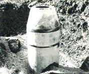
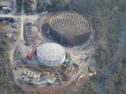
- Storage Tanks
- Groundwater Treatment Systems for Arsenic, Radon, Methane, and Hydrogen Sulfide
- Wastewater Treatment Plants
- Lift Stations
- Sludge Processing
- Reclaimed Water Systems
- Stormwater Pump Stations
PCDG specializes in water transmission projects and hydraulic system modeling and analysis, focusing on both large diameter water pipeline in congested rights-of-way and open country construction. Additionally, we design complex systems capable of being constructed in various open-cut and trenchless construction applications. We also model water distribution and sanitary sewer collection systems.
Water & Wastewater Projects
- RUSK, DUMBLE, PULK, AND EASTWOOD WATER MAIN: The project featured approximately 20,600 lf. of 4”, 6”, 8” and 12” dia. water mains. Project consisted of water main replacement in the area bounded by Rusk, Dumble, Polk, and Eastwood, TX. Project included 600 lf. of 4″, 8,755 lf. of 6″, 7,787 lf. of 8″, 3,400 lf. of 12″ water mains, replacement of fire hydrants and copper services lines.
- WATER MAIN REPLACEMENT LANGWOOD SECTION 2 AND WILSON COURT: This project featured replacement of approximately 29,200 linear feet of existing water mains, 8” and 12” for the City of Houston, TX.
- SURFACE WATER TRANSMISSION PROGRAM: This project featured the design of 8,900 feet of 48″ water main, 12 Access Manholes with Air Release Valves, 3 Tunneled Road Crossings, Tunneled Road Crossings constructed with steel liner plate as part of the City of Houston, TX’s program to provide surface water to the western parts of the city. The project was constructed in a heavily congested area, with apartments and townhouses lining the majority of the route. Tunneled crossings were designed for the crossing of Gessner Road (a 6-lane major thoroughfare), a Harris County Flood Control District drainage channel, and the Sam Houston Tollroad/Beltway 8.
- SURFACE WATER TRANSMISSION PROGRAM: This project featured the design of 9,950 linear feet of 36″ diameter and 1,450 linear feet of 30″ diameter new water mains on Wayside, Ranger and Pardee Streets for the City of Houston, TX. Special conditions include placement of 1,130 linear feet of 36” steel main within the traffic median of an existing bridge structure and 360′ of the 36″ diameter water main was placed in a new tunnel liner under I-45.
- 54” WATER MAIN, GREENWOOD RD. TO WEST 70TH STREET: The project was for installation of 12,200 linear feet of 54 inch diameter water main. This project is the first stage of major water transmission system improvements by the City of Shreveport, LA to correct transmission deficiencies between Treatment Plant and two major booster pumping stations/storage facilities located in the rapidly developing south Shreveport area. Pipeline is designed to meet the 1990 Design Year maximum day and maximum hour demands of 79 million gallons per day (mgd) and 126 mgd, respectively. Future extensions are programmed to meet Design Year 2030 conditions of 157 mgd and 251 mgd.
- CLEVELAND WATERLINE RELOCATION: Relocation of approximately 2,000 linear feet of existing water mains, 8″ and 12″ for City of Shreveport, LA.
- T.L. AMISS WATER TREATMENT PLANT: Design, prepare construction documents, estimates, bidding and construction phase services for the City of Shreveport, LA. Installation of water turbidity monitors at each filter bed to provide local turbidity readouts. The turbidity monitors were routed through a programmable logic controller; remote terminal units were needed for some of the filters. Construction work also included electrical wiring, controllers, plumbing lines, valves, fabrication of corrosive resistant mounting panels and concrete bases.
- T.L. AMISS WATER PURIFICATION PLANT: The filter-to-waste valves project designed the necessary facilities required to allow for the wasting of high turbidity filtered water that occurs immediately following the backwashing of high-rate sand filters for the City of Shreveport, LA. Physical improvements at the Amiss Water Treatment Plant included the installation of 4 inch and 8 inch bypass piping, with associated remote controlled valves, for 24 existing high rate sand filters.
- GREATER HOUSTON WASTEWATER PROGRAM EASTWOOD AREA SEWER IMPROVEMENTS: This project featured approximately 5,500 feet of 8″ and 12″ sanitary sewers replacing existing back lot sewers serving 72 single family residences. Construction replaced the existing sewers with new lines constructed within City street rights-of-way. This project involved replacement of two existing backlot sewers (designated for rehabilitation and relocation by the City’s Technical Services Branch due to missing top of pipe) into the city street Right of Way. The existing sewers were located along backlots between Walker and Rusk and between Woodside and Park Drive. Each sewer consisted of both 6 inch and 8 inch diameter pipe. The existing sewers were relocated to the street right of way due to permanent surface features (houses, garages, etc.) which prohibited access to the sewers for cleaning and rehabilitation. The existing sewers were replaced with new 8 inch diameter sewers located in the City street right of way. The final alignment was based on the results of the analysis of two alternate routes. One route involved installation of new 8 inch diameter sewers along Rusk, Walker, Park Drive and Woodside. The second route involved installation of new sewers in only two of the four City streets listed above to facilitate service of existing homes. Also considered was service connection requirements in the route evaluation. The new sewers discharge into an existing sanitary sewer line along Lockwood Street.
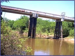
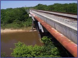
- SWEPCO RAILROAD:
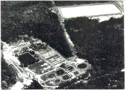
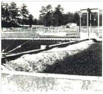
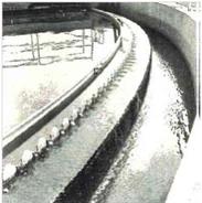
- FORT POLK WASTEWATER TREATMENT PLANT EXPANSION: A programmed expansion of the South Fort Polk Wastwater Treatment Plant, from 1.0 million gallons per day (mpg) to 5.2 mgd was designed. The wide scope of this project included: A Rigorous Testing Program; Feasibility Studies; Life Cost Comparisons; Project Design; Contract Drawings; and Specifications. Using the high trickling filter process, primary treatment is accomplished by screening, degriting, grease removal and primary clarification. Secondary treatment is by high rate filtration, clarification and disinfection. Other major components of the expansion were influent and effluent pumping, anerobic digestion facilities, sludge drying beds and a combined laboratory/operations building.
- BAFB EAST SEWER COLLECTION & DISPOSAL: Prepared the feasibility study, final plans and specifications, including bidding documents, to consolidate sewage collection and disposal serving Barksdale Air Force Base, East. The completed project collected discharges which were being treated by various types of small treatment facilities, including those serving the Capehart Housing area and the Bossier Base, and combined them into one system. The new system of gravity mains, pumping stations and force mains traverses a distance of 41,000 feet, discharges into Barksdale collection systems and finally into the Bossier City Red River Treatment Plant.
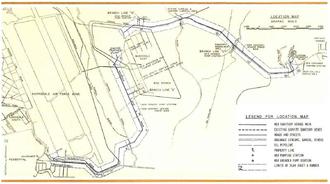
- RED RIVER INTERCEPTOR AND SEWAGE TREATMENT PLANT: This project, funded in part by a grant from the Environmental Protection Agency, provided sanitary sewage facilities for Bossier City, LA. This project consisted of: Infiltration/Inflow Analysis and Sewer System Survey of the existing sewerage collection system; Facility Plan, including Environmental Assessment, recommending improvements to and the rehabilitation of the existing collection system, life cycle cost analysis of various treatment options and the environmental impacts of each, outlining the basic design of the selected treatment scheme and collection system improvements; Project Design Phase, including preparation of construction drawings, specifications and bidding documents; and monitoring the construction of the project.
- NORTHEAST BOSSIER WATER TREATMENT PLANT: Bossier City, strategically located for rapid growth, was severely handicapped by not having an independent water supply and an inadequate distribution system. The Master Plan developed included demographic projection, network system analysis, rate studies, suggested methods of financing, and proposed the system be designed and constructed in two phases. Prepared design and construction plans and conducted construction observation.
Raw water was transmitted from Red River to a water reservoir based upon selective pumping of river water to reservoir to treatment plant. The treatment plant and system was designed for 20.0 mgd.
The distribution system included upgrading with a main distribution system of 10” to 30” dia. pipe lines which supplied a network of 6” and 8” distribution lines supported by a 1.5 million gallon elevated tank. Bossier City is the only city utilizing Red River water and the sole source for its water supply.